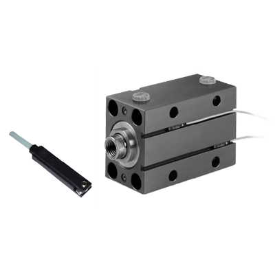
Short stroke compact hydraulic cylinders
Model X - Variants
Categories
Cylinders
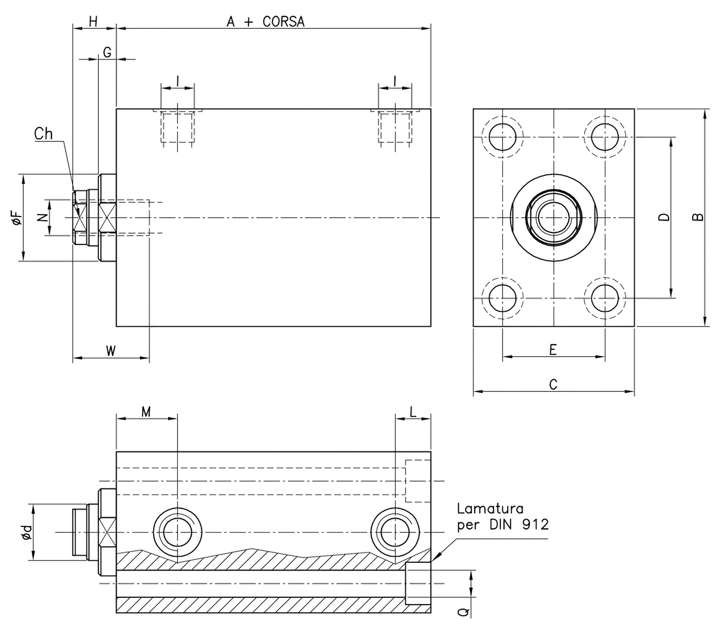
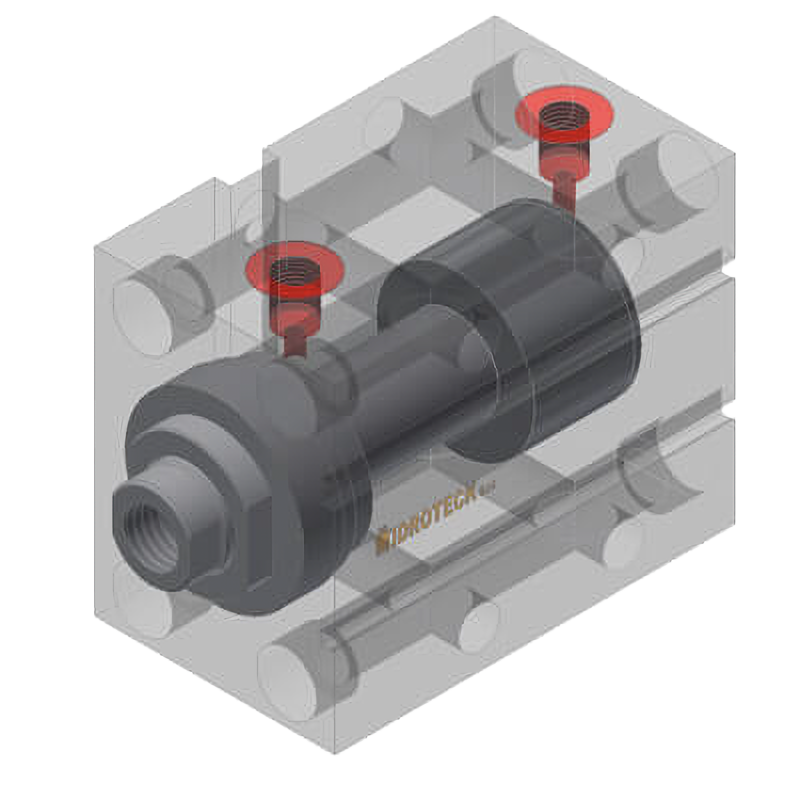
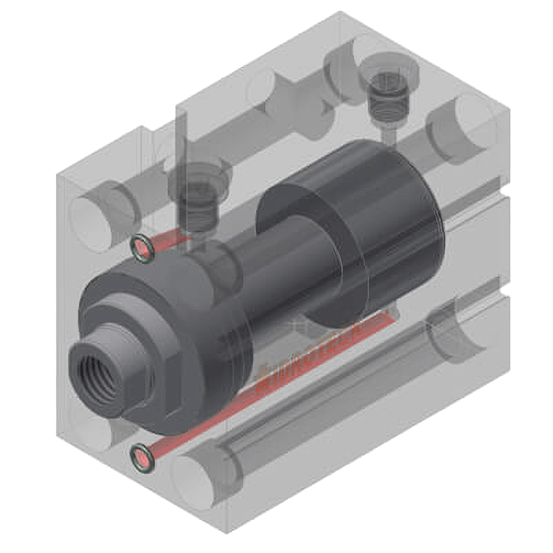
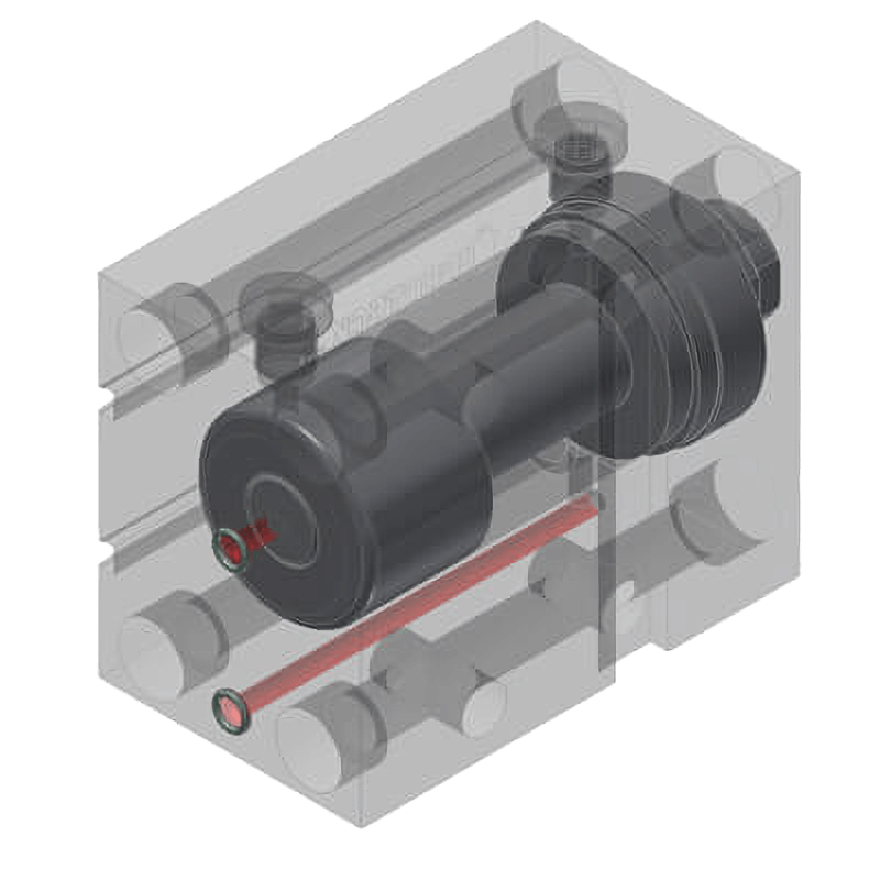
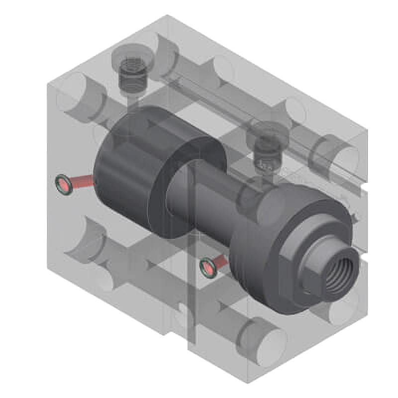
Mod. X/01: longitudinal holes and front and rear lamination
- Standard strokes: 20 - 50 - 75 - 100 mm;
- In ø25 bore cylinders the grooves for the sensors are not through the entire length of the body, but blind on the rod side;
- It is recommended to use high-strength screws for fastening.
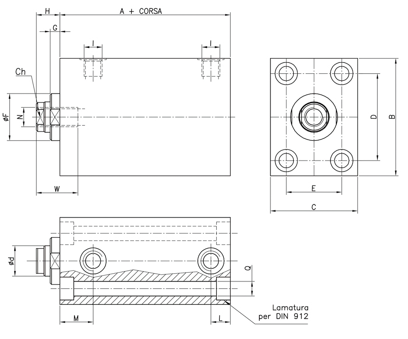
Mod. X/01
| Al. | d | A+ | B | C | Ch | D | E | F | G | H | I | L | M | N | Q | W |
|---|---|---|---|---|---|---|---|---|---|---|---|---|---|---|---|---|
| 25 | 18 | 57 | 65 | 45 | 14 | 50 | 30 | 30 | 6.5 | 14 | G1/4" | 12 | 22 | M10 | 8.5 | 24 |
| 32 | 22 | 60 | 75 | 55 | 18 | 55 | 35 | 34 | 8 | 15 | G1/4" | 12 | 22 | M12 | 10.5 | 24 |
| 40 | 22 | 73 | 85 | 63 | 18 | 63 | 40 | 34 | 7 | 17 | G1/4" | 14 | 24 | M14 | 10.5 | 30 |
| 50 | 28 | 75 | 100 | 75 | 24 | 76 | 45 | 42 | 8 | 20 | G1/4" | 16 | 25 | M20 | 13 | 35 |
| 63 | 28 | 85 | 115 | 90 | 24 | 90 | 55 | 50 | 7 | 20 | G3/8" | 21 | 29 | M20 | 13 | 35 |
| 80 | 36 | 100 | 140 | 110 | 32 | 110 | 75 | 60 | 7 | 20 | G1/2" | 25 | 35 | M27 | 17 | 45 |
| 100 | 45 | 110 | 170 | 140 | 40 | 135 | 95 | 72 | 8 | 25 | G1/2" | 28 | 37 | M33 | 17 | 55 |
Mod. X/02: transversal holes with key
- Standard strokes: 20 - 50 - 75 - 100 mm;
- T(*) Stroke 20 mm without holes;
- In ø25 bore cylinders the grooves for the sensors are not through the entire length of the body, but blind on the rod side;
- It is recommended to use high-strength screws for fastening.
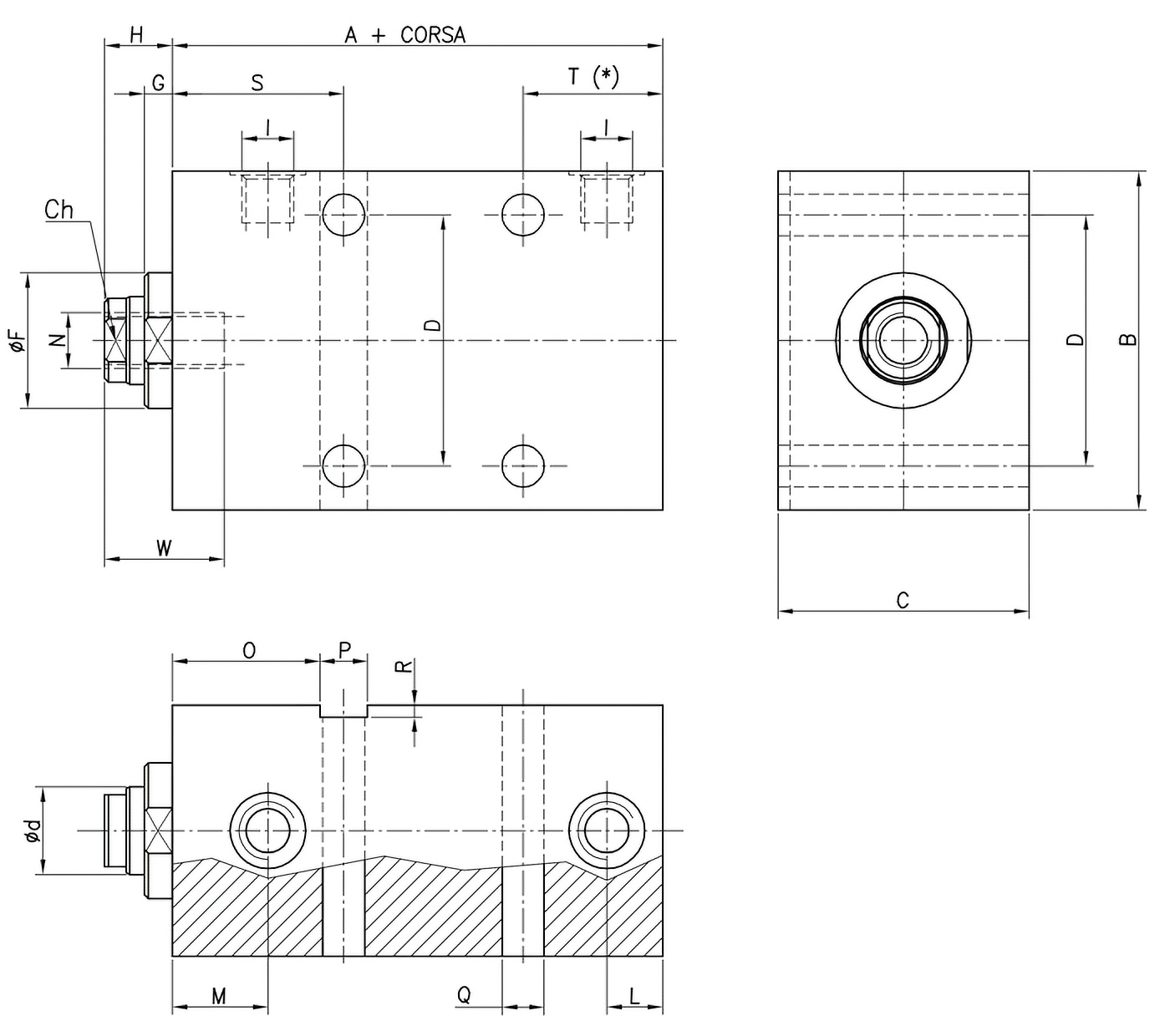
Mod. X/02
| Al. | d | A+ | B | C | Ch | D | E | F | G | H | I | L | M | N | O | P | Q | R | S | T | W |
|---|---|---|---|---|---|---|---|---|---|---|---|---|---|---|---|---|---|---|---|---|---|
| 25 | 18 | 57 | 65 | 45 | 14 | 50 | 30 | 6.5 | 14 | G1/4" | 12 | 22 | M10 | 32 | 10 | 8.5 | 2 | 37 | 30 | 24 | |
| 32 | 22 | 60 | 75 | 55 | 18 | 55 | 34 | 8 | 15 | G1/4" | 12 | 22 | M12 | 34 | 12 | 10.5 | 3 | 40 | 30 | 24 | |
| 40 | 22 | 73 | 85 | 63 | 18 | 63 | 34 | 7 | 17 | G1/4" | 14 | 24 | M14 | 37 | 12 | 10.5 | 3 | 43 | 35 | 30 | |
| 50 | 28 | 75 | 100 | 75 | 24 | 76 | 42 | 8 | 20 | G1/4" | 16 | 25 | M20 | 37.5 | 15 | 13 | 5 | 45 | 35 | 35 | |
| 63 | 28 | 85 | 115 | 90 | 24 | 90 | 50 | 7 | 20 | G3/8" | 21 | 29 | M20 | 47.5 | 15 | 13 | 5 | 55 | 40 | 35 | |
| 80 | 36 | 100 | 140 | 110 | 32 | 110 | 60 | 7 | 20 | G1/2" | 25 | 35 | M27 | 50 | 20 | 17 | 5 | 60 | 50 | 45 | |
| 100 | 45 | 110 | 170 | 140 | 40 | 135 | 72 | 8 | 25 | G1/2" | 28 | 37 | M33 | 60 | 20 | 17 | 5 | 70 | 60 | 55 |
Mod. X/03: threaded front holes
- Standard strokes: 20 - 50 - 75 - 100 mm;
- T(*) Stroke 20 mm without holes;
- In ø25 bore cylinders the grooves for the sensors are not through the entire length of the body, but blind on the rod side;
- It is recommended to use high-strength screws for fastening.
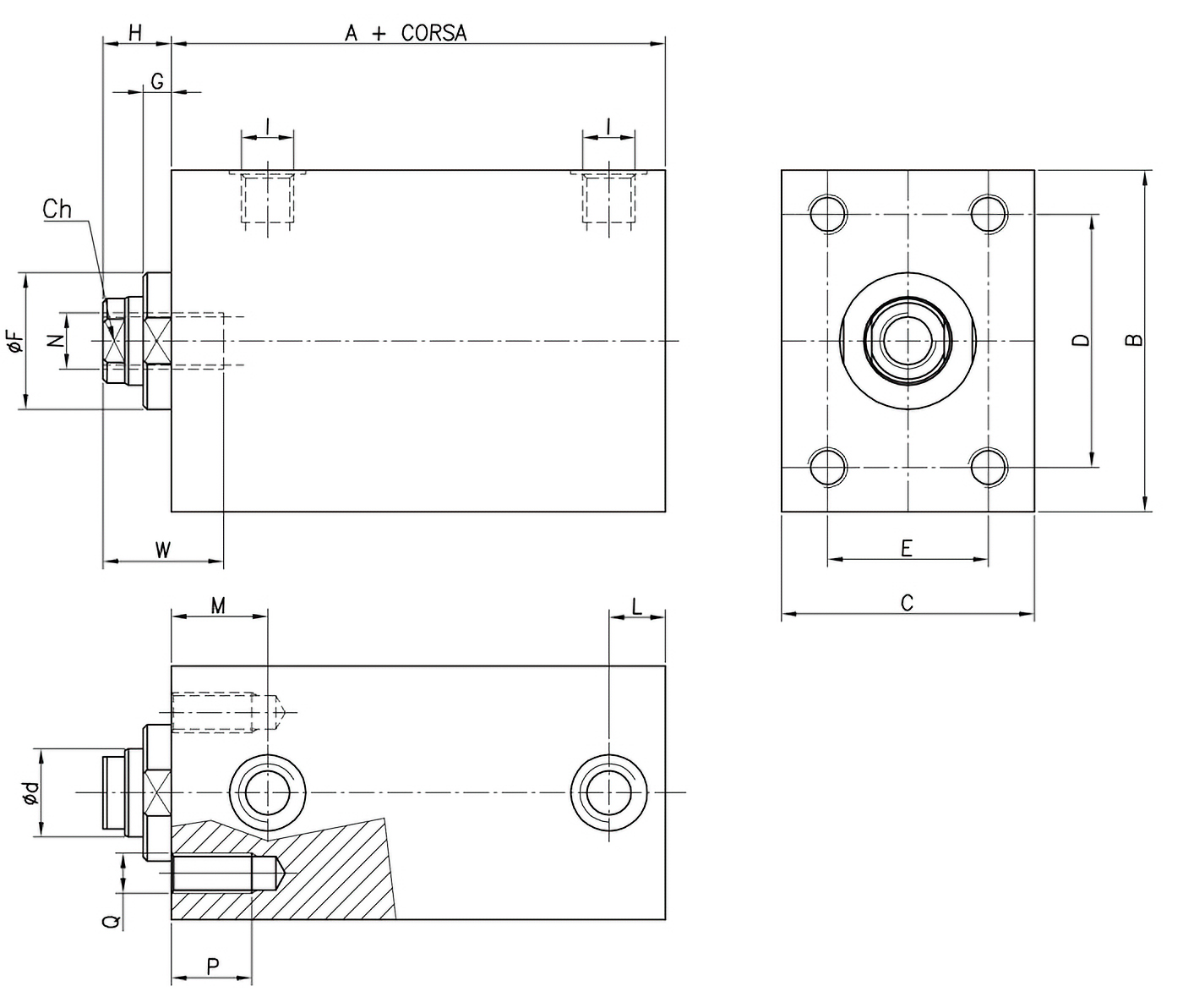
Mod. X/03
| Al. | d | A+ | B | C | Ch | D | E | F | G | H | I | L | M | N | P | Q | W |
|---|---|---|---|---|---|---|---|---|---|---|---|---|---|---|---|---|---|
| 25 | 18 | 57 | 65 | 45 | 14 | 50 | 30 | 30 | 6.5 | 14 | G1/4" | 12 | 22 | M10 | 16 | M8 | 24 |
| 32 | 22 | 60 | 75 | 55 | 18 | 55 | 35 | 34 | 8 | 15 | G1/4" | 12 | 22 | M12 | 18 | M10 | 24 |
| 40 | 22 | 73 | 85 | 63 | 18 | 63 | 40 | 34 | 7 | 17 | G1/4" | 14 | 24 | M14 | 18 | M10 | 30 |
| 50 | 28 | 75 | 100 | 75 | 24 | 76 | 45 | 42 | 8 | 20 | G1/4" | 16 | 25 | M20 | 20 | M12 | 35 |
| 63 | 28 | 85 | 115 | 90 | 24 | 90 | 55 | 50 | 7 | 20 | G3/8" | 21 | 29 | M20 | 20 | M12 | 35 |
| 80 | 36 | 100 | 140 | 110 | 32 | 110 | 75 | 60 | 7 | 20 | G1/2" | 25 | 35 | M27 | 24 | M16 | 45 |
| 100 | 45 | 110 | 170 | 140 | 40 | 135 | 95 | 72 | 8 | 25 | G1/2" | 28 | 37 | M33 | 24 | M16 | 55 |
Mod. X/04: threaded rear holes
- Standard strokes: 20 - 50 - 75 - 100 mm;
- T(*) Stroke 20 mm without holes;
- In ø25 bore cylinders the grooves for the sensors are not through the entire length of the body, but blind on the rod side;
- It is recommended to use high-strength screws for fastening.
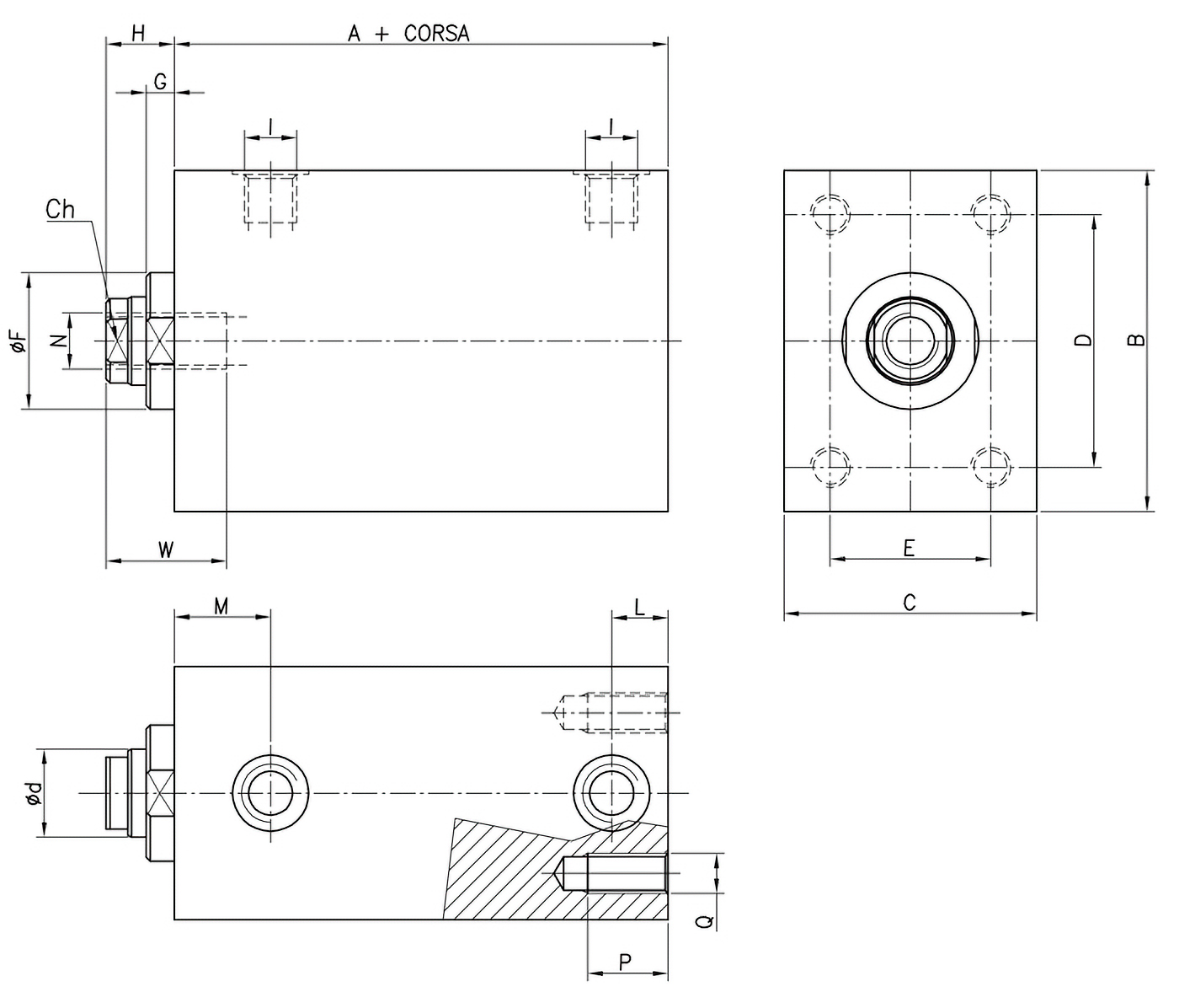
Mod. X/04
| Al. | d | A+ | B | C | Ch | D | E | F | G | H | I | L | M | N | P | Q | W |
|---|---|---|---|---|---|---|---|---|---|---|---|---|---|---|---|---|---|
| 25 | 18 | 57 | 65 | 45 | 14 | 50 | 30 | 30 | 6.5 | 14 | G1/4" | 12 | 22 | M10 | 16 | M8 | 24 |
| 32 | 22 | 60 | 75 | 55 | 18 | 55 | 35 | 34 | 8 | 15 | G1/4" | 12 | 22 | M12 | 18 | M10 | 24 |
| 40 | 22 | 73 | 85 | 63 | 18 | 63 | 40 | 34 | 7 | 17 | G1/4" | 14 | 24 | M14 | 18 | M10 | 30 |
| 50 | 28 | 75 | 100 | 75 | 24 | 76 | 45 | 42 | 8 | 20 | G1/4" | 16 | 25 | M20 | 20 | M12 | 35 |
| 63 | 28 | 85 | 115 | 90 | 24 | 90 | 55 | 50 | 7 | 20 | G3/8" | 21 | 29 | M20 | 20 | M12 | 35 |
| 80 | 36 | 100 | 140 | 110 | 32 | 110 | 75 | 60 | 7 | 20 | G1/2" | 25 | 35 | M27 | 24 | M16 | 45 |
| 100 | 45 | 110 | 170 | 140 | 40 | 135 | 95 | 72 | 8 | 25 | G1/2" | 28 | 37 | M33 | 24 | M16 | 55 |
Mod. X/05: longitudinal holes and front lamination
- Standard strokes: 20 - 50 - 75 - 100 mm;
- T(*) Stroke 20 mm without holes;
- In ø25 bore cylinders the grooves for the sensors are not through the entire length of the body, but blind on the rod side;
- It is recommended to use high-strength screws for fastening.
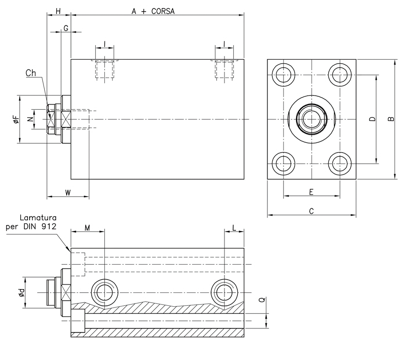
Mod. X/05
| Al. | d | A+ | B | C | Ch | D | E | F | G | H | I | L | M | N | Q | W |
|---|---|---|---|---|---|---|---|---|---|---|---|---|---|---|---|---|
| 25 | 18 | 57 | 65 | 45 | 14 | 50 | 30 | 30 | 6.5 | 14 | G1/4" | 12 | 22 | M10 | 8.5 | 24 |
| 32 | 22 | 60 | 75 | 55 | 18 | 55 | 35 | 34 | 8 | 15 | G1/4" | 12 | 22 | M12 | 10.5 | 24 |
| 40 | 22 | 73 | 85 | 63 | 18 | 63 | 40 | 34 | 7 | 17 | G1/4" | 14 | 24 | M14 | 10.5 | 30 |
| 50 | 28 | 75 | 100 | 75 | 24 | 76 | 45 | 42 | 8 | 20 | G1/4" | 16 | 25 | M20 | 13 | 35 |
| 63 | 28 | 85 | 115 | 90 | 24 | 90 | 55 | 50 | 7 | 20 | G3/8" | 21 | 29 | M20 | 13 | 35 |
| 80 | 36 | 100 | 140 | 110 | 32 | 110 | 75 | 60 | 7 | 20 | G1/2" | 25 | 35 | M27 | 17 | 45 |
| 100 | 45 | 110 | 170 | 140 | 40 | 135 | 95 | 72 | 8 | 25 | G1/2" | 28 | 37 | M33 | 17 | 55 |
Mod. X/06: longitudinal holes and rear lamination
- Standard strokes: 20 - 50 - 75 - 100 mm;
- T(*) Stroke 20 mm without holes;
- In ø25 bore cylinders the grooves for the sensors are not through the entire length of the body, but blind on the rod side;
- It is recommended to use high-strength screws for fastening.
Mod. X/06
| Al. | d | A+ | B | C | Ch | D | E | F | G | H | I | L | M | N | Q | W |
|---|---|---|---|---|---|---|---|---|---|---|---|---|---|---|---|---|
| 25 | 18 | 57 | 65 | 45 | 14 | 50 | 30 | 30 | 6.5 | 14 | G1/4" | 12 | 22 | M10 | 8.5 | 24 |
| 32 | 22 | 60 | 75 | 55 | 18 | 55 | 35 | 34 | 8 | 15 | G1/4" | 12 | 22 | M12 | 10.5 | 24 |
| 40 | 22 | 73 | 85 | 63 | 18 | 63 | 40 | 34 | 7 | 17 | G1/4" | 14 | 24 | M14 | 10.5 | 30 |
| 50 | 28 | 75 | 100 | 75 | 24 | 76 | 45 | 42 | 8 | 20 | G1/4" | 16 | 25 | M20 | 13 | 35 |
| 63 | 28 | 85 | 115 | 90 | 24 | 90 | 55 | 50 | 7 | 20 | G3/8" | 21 | 29 | M20 | 13 | 35 |
| 80 | 36 | 100 | 140 | 110 | 32 | 110 | 75 | 60 | 7 | 20 | G1/2" | 25 | 35 | M27 | 17 | 45 |
| 100 | 45 | 110 | 170 | 140 | 40 | 135 | 95 | 72 | 8 | 25 | G1/2" | 28 | 37 | M33 | 17 | 55 |
FT-XT Steel Series
Discover all models
Model X - Variants
Discover all accessories